MRS - the Modular Rocket SystemConstruction DetailsAfter SkyDream, I decided to build a couple of 3" rockets, one for my up-and-coming GPARS project, and another to try Dual Deployment, eventually to be called Double Trouble. Since I was gonna be building two rockets, I figured, why not leverage off of my past experiences and build a modular set of rockets with interchangeable parts. Particularly important to me, after repairing SkyDream twice, was to ensure from the beginning that I would be able to easily replace any tubes that got zippered. Also, I decided that both rockets should make use of altimeter deployment, as it's supposed to be more reliable, and at least once I had zippered SkyDream cuz it didn't open at the right time. Plus I wanted to fly 38mm or 54mm motors without using motor adaptors. For these reasons, and because I had almost exactly the right number of 3" tubes laying around, I designed this Modular Rocket System. 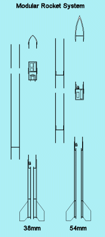
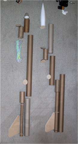
The MRS properly includes only the two fin cans and bottom body tubes shown in the drawing/picture above, which are generally interchangeable. The GPARS and DoubleTrouble electronics modules and everything above them (the upper dual deployment body tube, the little body tube on GPARS, and the nosecones) are more properly considered parts of those particular rockets. So this webpage details only the construction of the fin cans and body tubes. 1. Fin CanThe fin cans were constructed in the usual way. I cut 1/8" fins for the 38mm rocket, and 1/4" fins for the 54mm rocket out of modelling plywood. I tried various ways of cutting centering rings including the scroll saw (slow and hard) and hole saws (hard and expensive, but worth it, to get the right sizes). I cut a bunch of centering rings of various sizes out of both kinds of plywood. 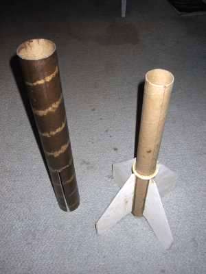
The fins are glued to the motor tubes and the forward centering ring with 5min epoxy. After cutting the fin slots in the tubes (using a jury rigged vise-guide for my dremel), the spirals are filled with modelling spackle, the tubes sanded, and then laminated with a layer of 2oz fiberglass. The motor assembly is inserted into the back of the rocket, with 30min epoxy on all contact points (at least four glue sessions), including the inside where the fins meet the body tube. The fin cans are finished by glueing in the aft centering ring (after planning the motor retention!!!) and making 5 min epoxy filets for each fin (doing two out of eight fillets per glue session). It takes a long time to do all the glueing on these parts! 2. Motor Retention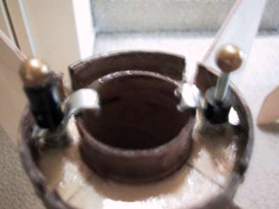
Fashioned up some motor retention for the 38mm motor. Before I glued in the aft centering ring, I installed and epoxied two downward facing bolts to which I could later attach hardware. I ended up bending little brackets out of stock pieces as shown above. The spacers ended up not being used. A couple of nuts are permanently attached, then the brackets are held on with just the cap nuts. Haven't had any problems with these! 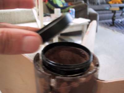
On the 54mm I used the AeroPac retention system that I bought but never installed on SkyDream. These things are a little rough to put on. They are very tight fitting and it's hard to shrink the end of the motor tube (sanding just roughs it up). Plus it has a tendency to get epoxy on it during the building of the fin cans. I had to work it for some time before I could get it to go on. Then after glueing, I had to rout out about 1/8" of tube cuz I hadn't gotten the spacing exactly right. These devices are neat, but a little hard to install. 3. Ejection Charge SocketThe ejection charge sockets are made from PVC pipe based on the needed size of the charge. After a bit of testing (on the 4th of July!), I determined that 3/4" OD ejection charges were better. When I put the required amount of FFFF powder into a 1/2" tube, it went off with a noticable "bang!". When I put a gram or so into the 3/4" charges, they just go "pffft", which I find much more palatable. So the socket is 3/4" ID (1" OD) pvc. I use the dremel-sander to remove about 1/16" from the inside of the charge holder so that the charges will slide in and out. After soldering wires onto them, the brass contacts are bent over inside the tube and epoxied on the outside. 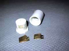
The entire assembly is bolted into the side of the fin can coupling tube. The other end of the wires are soldered to some brass 8/32 nuts, which are then epoxied onto the sides of the coupling tubes. The electricity from the altimeter will make its way from the outside of the rocket by screws carrying it to the nuts on the side of the tube. It turned out that this was one of the most crucial parts of the MRS ... these holes have to be perfectly aligned for both fin cans and body tubes to be interchangable! The charges themselves are 1" pieces of 3/4" OD pvc, plugged with a slice of broomstick and glue, with two sides slightly flattened with the dremel-sander, and 1/16" holes drilled in the bottoms. The ignitor leads are bent back up the charge, and taped near the top. The powder and some fireproof wadding is placed in the charge and a layer of masking tape is placed on top, but NOT OVER THE EDGES, to keep the forces to a minimum. All you want from an ejection charge is air expansion! 4. Body Tube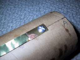
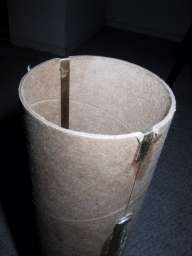
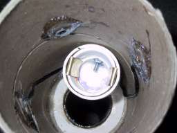
The body tubes are designed to carry the charge from the altimeter to the fin can. There are brass foil strips, soldered to brass metal strips, that provide connectors on both ends. The bottom connectors couple with the nuts on the inside of the fin can with metal screws, and the top ones are passed thru slits in the tube and bent over the top, so as to make sliding contact with the electronics module as it is inserted into the body tube. 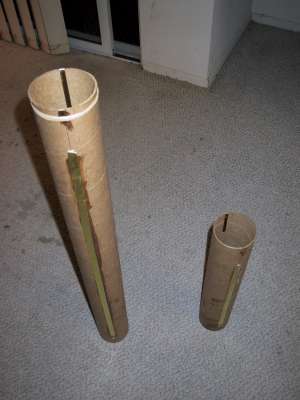
After assembly, the body tube spirals and any little edges on the foil were filled with modellers spackle. After sanding, the body tubes were laminated with 1 oz fiberglass.
5. Gas and Zipper ProtectionIn order to keep down some of the hot gasses and particles from the ejection charge, to provide a platform for the shock cord and parachute to rest on (so they don't land directly on the ejection charge), and to provide a location to attach the shock cord, there is a plywood baffle installed towards the bottom of each body tube. A 1" nylon strap with quick-link brings the the cord out of the body. All bungee cord is considered temprorary and removable. One cool thing I discovered here is that you can sometimes get Nomex for free from fire departments that cycle out their used clothing. I make squares of it, with slots thru which the shock cord passes. 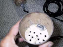
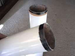
For zipper protection, I laminated two layers of 1/2" carbon fiber around the mouth of each tube. This prevents, somewhat, the shock cord from cutting thru the body tube on high-speed deployments. In the picture on the right, above, the black strip is the Carbon Fiber. Very tough stuff.
6. Finish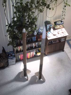
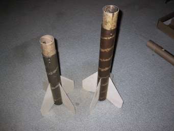
The Epoxy finish is rough and fine sanded, and then the rockets are primed, sanded, painted, sanded, and painted again. That is where they are in the photo below. After that, I put the lettering on them (with masking and flat black paint), and then put on 3 coats of klear-cote. Whew, a lot of work, and thats not even counting the electronics! 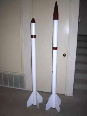
|