Rocket #8 - GPARS (GPS Automatic Recovery System)Construction DetailsGPARS really is just the top 1/3 or so of the rocket. Apart from the "Modular Rocket System", which provides the fins and body tubes, GPARS consists of the electronics module, and nosecone. But there's a lot of stuff packed into those two little things. 1. Servo AssemblyThe construction began with the Servo Assembly. I made a u-shaped piece out of 1" pine to hold the servo to the base plate. The base plate itself is a 1/8" centering ring and a 1/4" bulkhead. Three threaded rods hold the whole thing together. The Servo Assembly includes a metal spacer to keep the mid-bulkhead level. I fashioned the control arm out of a metal bracket, glued and screwed to a servo horn. 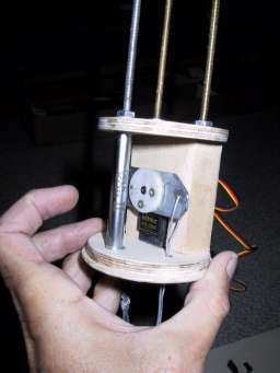
I figure that this piece has to be pretty solid, since it might bear the brunt of the forces during ejection. 2. Innards (Servo, Radio, Battery, and Altimeter)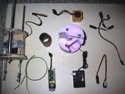
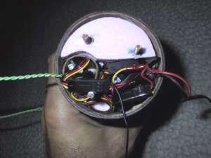
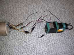
In the diagram above you see everything that goes into the electronics-module proper, including the Servo Assembly, Battery, a 29mm tube to hold the altimeter, the foam insert, the wiring harness, ejection charge cable, altimeter, radio, and power/arming switch. I created the wiring harness and switch from standard r/c connectors and a four pin dip switch. Everything is soldered and insulated with heat shrink tubing. 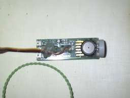
I soldered a cable onto the board (details left to the reader) to allow me to connect the battery and arming switch to the altimeter. Hot glue was applied for strain relief. The ejection charge cable runs thru the tube, out holes in the side and is soldered to two sheets of brass foil (not shown) that are wrapped around the aft coupling section. An outer ring of standard body tube, 2" in length, covers the wire/solder joints and the top of the brass foil. 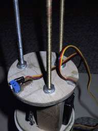
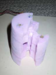
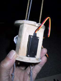
The switch is glued onto the mid-bulkhead, and a foam insert was fashioned by cutting layers out of a sheet of 1" pink insulating foam. The insert has all kinds of holes and passages to allow all of the wires from the various components to be brought up to the top of the tube. Below we show the assembly before inserting in the tube. The whole thing is topped off with a 1/4" bulkhead, with washers, lock washers, and nuts. The total length is 6.5", so there's not a lot of room left after everything is jammed in there. A small piece of foam padding gets stuffed in whatever room remains before flight. 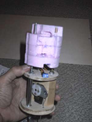
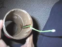
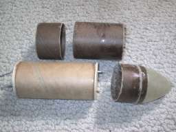
3. Nose ConeI fashioned the nose cone from the packaging materials for a 3" R/C airplane propeller nosecone. It fits just right over a coupling tube, so I laminated it on the inside with 3 or 4 layers of 1 oz cloth. In the picture on the right, below, you can see the tubes ready for final assembly. The small section of body tube will be glued to the eletronics module. The larger section will have retaining screws as will the nose cone. 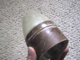
4. GPS Receiver and Servo ControllerThe GPS Reciever and Servo Control are not in the electronics module proper, but rather in the forward payload section (the nose cone and tube). All of the necessary connectors from the electronics module are routed out of the top of the module and secured with hot-glue. That includes: the antenna for the radio, a power connector to re-charge the battery, the radio servo outputs and the servo input. The GPS receiver can be removed by connecting the servo intput and outputs together. When in place, it intercepts the control from the radio based on the state of the second channel (the Servo Controller "enable"). 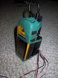
5. Final AssemblyIn the picture below you can see the GPARS electronics module, proper, with the outer tube glued on (and painted red), along with the brass foil contacts that cover the bottom portion of the coupling tube. The brass portion slides into the top of the "modular rocket sysetm" body tube to make contact with the brass contacts inside of it. You can also see the hole for access to the switches. This same hole is used to allow atmospheric pressure into the module for the altimeter. 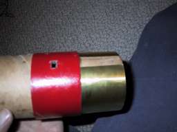
|